
Contact Us
Top 10 Tips for Mastering 18650 Battery Packs?
mastering 18650 battery packs requires more than arranging cylindrical cells and adding nickel strips. It demands disciplined selection, electrical calculation, thermal awareness, and careful verification. A single weak cell can reduce pack performance, increase heat, and shorten service life. Small mistakes become visible quickly.
The International Energy Agency reported that global lithium-ion battery demand reached about 750 GWh in 2023. BloombergNEF also reported an average lithium-ion battery-pack price of $139 per kWh that year. These figures show a maturing industry, but they do not make every homemade pack reliable. Cell chemistry, age, internal resistance, insulation, and protection design still matter greatly. The Battery University founder Isidor Buchmann offers a useful reminder: “A battery is like a human being. It needs exercise.” His statement supports balanced use, measured charging, and realistic maintenance.
This guide presents the top 10 tips for mastering 18650 battery packs. It focuses on practical decisions, from matching cells to checking voltage under load. You will see why a multimeter is not enough. A proper spot welder, insulated workspace, fuse strategy, and battery-management system can prevent avoidable failures. Yet this topic deserves humility. Manufacturer data may be incomplete. Used cells may look identical but behave differently. Even an experienced builder can overlook heat paths or poor insulation. Reliable work means testing, documenting, and reviewing each assumption before energizing the pack. Safety must remain more important than capacity, cost, or speed.
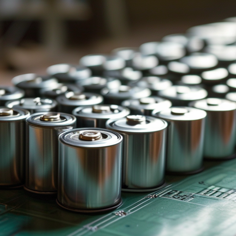
Understand 18650 Cell Types, Ratings, and Safe Operating Limits
Top 10 Tips for Mastering 18650 Battery Packs
Understand 18650 cell types before connecting cells. Protected cells include a safety circuit, while unprotected cells require external protection. Common lithium-ion chemistries differ in voltage, capacity, cycle life, and thermal behavior. Most 18650 cells have a nominal voltage near 3.6 or 3.7 volts. Their charging limit is usually 4.2 volts, but always verify the datasheet. Never guess.
Tip 1: Match cells by chemistry, capacity, age, and measured internal resistance. Tip 2: Use a charger designed for the exact cell chemistry. Tip 3: Add a suitable battery-management system for overcharge, over-discharge, overcurrent, and balancing protection. IEC 62133-2 and UL 1642 provide useful safety benchmarks for rechargeable lithium cells. The IEA’s Global EV Outlook 2024 reported more than 750 GWh of battery demand in the energy sector during 2023. Scale is growing, but safety margins remain personal responsibilities.
Tip 4: Keep continuous discharge current below the manufacturer’s tested rating. Pulse ratings can mislead. Tip 5: Stop using cells with dents, rust, torn wraps, swelling, or unusual heat. Tip 6: Measure every parallel group before assembly. A 0.1-volt mismatch deserves investigation. Tip 7: Use insulated cell holders, nickel-based interconnects, and a nonflammable enclosure. Tip 8: Avoid soldering directly to cell terminals when possible. Tip 9: Record voltage, temperature, and capacity during testing. I once trusted matching labels too quickly; real measurements exposed unequal aging. Tip 10: Review the design against UN 38.3 transport testing and applicable local standards. Mistakes become expensive fast.
Top 10 Tips for Mastering 18650 Battery Packs? - Understand 18650 Cell Types, Ratings, and Safe Operating Limits
| No. | Mastery Tip | Key Data Dimension | Typical or Reference Values | Safe Operating Practice |
|---|---|---|---|---|
| 1 | Identify the cell chemistry | Chemistry, nominal voltage, and charge limit | Standard NMC/NCA lithium-ion cells: approximately 3.6–3.7 V nominal and 4.20 V maximum charge voltage. Lithium iron phosphate cells: approximately 3.2–3.3 V nominal and 3.65 V maximum charge voltage. | Never use a charger or BMS intended for one chemistry with another chemistry unless the voltage profile is specifically compatible. |
| 2 | Read every cell rating | Capacity, continuous discharge current, and maximum charge current | Capacity is commonly stated in mAh or Ah. Discharge capability can range from roughly 2 A for energy-oriented cells to more than 20 A for high-power cells. Charge limits are often around 0.5C–1C, depending on the datasheet. | Use the manufacturer’s datasheet for the exact cell. Do not infer current capability from capacity, appearance, or printed markings alone. |
| 3 | Calculate series and parallel groups | Pack voltage, capacity, and energy | Series count increases voltage: Vnominal ≈ 3.6–3.7 × S for common NMC/NCA cells. Parallel count increases capacity: Ahpack ≈ Ahcell × P. Approximate energy: Wh ≈ Vnominal × Ah. | A 4S3P pack using 3.6 V, 2.5 Ah cells is approximately 14.4 V nominal, 7.5 Ah, and 108 Wh. Confirm maximum and minimum pack voltage before connection. |
| 4 | Respect voltage limits | Maximum charge voltage and minimum discharge voltage | Common 4.20 V lithium-ion cells should not be charged above 4.20 V per cell. Many systems use a discharge cutoff near 2.5–3.0 V per cell, depending on the cell and application. | Set charger and BMS thresholds from the exact datasheet. Avoid routinely discharging to the absolute minimum because it increases stress and reduces cycle life. |
| 5 | Use the correct charging method | Constant-current/constant-voltage charging | A typical lithium-ion charging profile is CC/CV: constant current until 4.20 V per cell, followed by constant voltage until the current tapers to the specified termination level. | Use a charger designed for the pack’s chemistry and series count. Do not use a simple power supply without appropriate voltage regulation, current control, and protection. |
| 6 | Design for current and heat | Load current, C-rate, resistance, and temperature | C-rate = current ÷ capacity in Ah. For example, 5 A from a 2.5 Ah cell equals 2C. Higher current increases voltage sag and heat according to approximately P = I²R. | Keep continuous current below the cell’s rated limit, provide ventilation, and stop operation if the pack becomes unusually hot, swells, vents, or produces an odor. |
| 7 | Match cells before assembly | Capacity, internal resistance, age, and state of charge | Cells connected in parallel should have closely matched voltage before connection. Cells in a series string should have similar capacity and internal resistance to reduce imbalance. | Do not mix unknown, damaged, recycled, or visibly different cells in the same pack. Test capacity and voltage, and reject cells with abnormal self-discharge. |
| 8 | Install protection and balancing | BMS functions and series configuration | A suitable BMS should match the number of series cells and provide overcharge, over-discharge, overcurrent, short-circuit, and temperature protection. Passive balancing commonly operates near the upper voltage region. | Select a BMS with compatible chemistry settings, current rating, sensor placement, and wiring. A BMS is a safety layer, not a substitute for correct design. |
| 9 | Control storage conditions | Storage state of charge, temperature, and environment | For extended storage, approximately 40%–60% state of charge is commonly recommended. A cool, dry, nonflammable location is preferable; avoid direct sunlight, freezing conditions, and high heat. | Inspect stored packs periodically for voltage loss, corrosion, swelling, or physical damage. Keep terminals covered to prevent accidental short circuits. |
| 10 | Build and test safely | Insulation, interconnects, testing, and fault prevention | Use insulated holders or appropriate cell spacers, nickel strip or approved interconnects, a fuse where appropriate, and reliable insulation around positive terminals. Spot welding is generally preferred over direct soldering to cells. | Check polarity, cell-group voltage, continuity, insulation, BMS operation, and temperature under a controlled load before regular use. Never bypass protection or deliberately short a cell. |
Reference note: Exact voltage, current, temperature, charging, and cutoff limits vary by cell model and chemistry. Always verify the original cell datasheet and follow applicable electrical and fire-safety requirements.